
To understand literally anything that I can explain after this I have to first explain what BIM is, and in accordance with that what Revit and Navisworks is. There are countless programs beyond that to model in, such as AutoCad :(, however the only ones I have ever used are those two, and while AutoCad can be useful for drawing ITM’s, which we will talk about later, the industry standard for modeling and most BIM work is Revit and Navisworks. BIM is Building Information Modeling, it is the process of creating and managing the information about a building or infrastructure project throughout the life cycle of its construction (and sometimes beyond that). BIM uses 3D modeling to imitate the geometry of a building and its systems, everything about the building, from its walls and doors to the plumbing and its fire protection fall under BIM. It is a process that involves a LOT of collaboration from engineers to foreman to the simplest field workers, and people like me, modelers. But none of this is possible without the programs to make it all happen.

Revit
Revit is a BIM software, developed by Autodesk for the purpose of modeling, documenting/scheduling, dimensioning and spooling.
Modeling
Modeling is basically the process of creating the system itself, it’s the most important part of the entire process and what defines BIM work. You review the contract drawings provided by the client then model based on that, contract drawings are basically the original design created by the engineers, our job is to take the stuff they put down and make it actually work. So you model the system out to see if anything is clashing with other systems, make sure the flow isn’t bad, or make adjustments to save money. Of course if you want to change anything major you have to send a change order in or talk to the engineers to make sure it’s actually possible to do that but this is the core of BIM work.

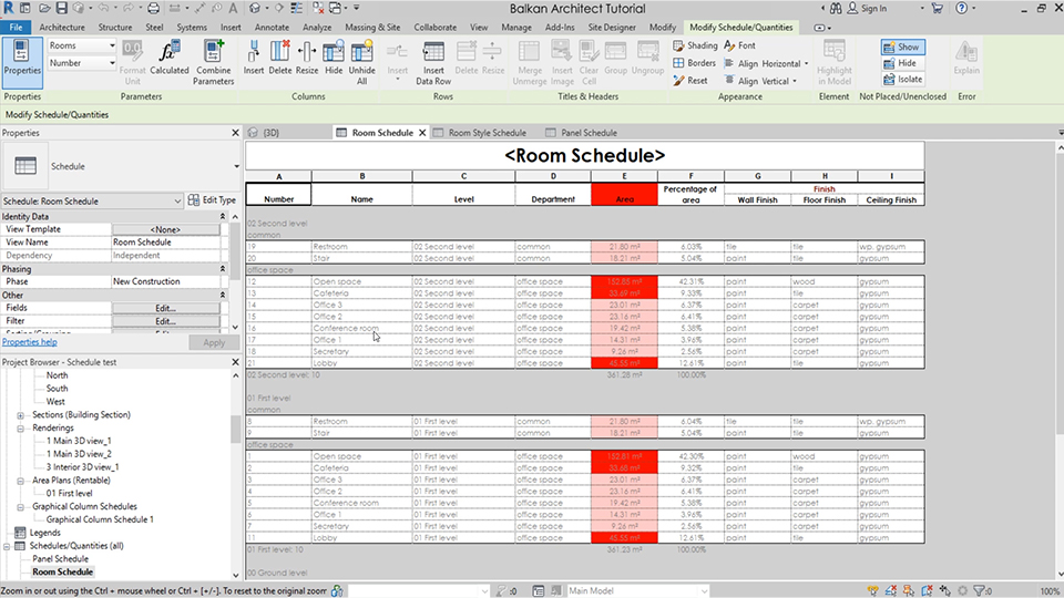
Documenting or Scheduling
Documenting or scheduling fall under the same umbrella so I decided to include them both here. Documenting is the process of keeping track of all your changes, your modeling, how many valves you have in the system, the pipe material, the pipe size etc. And scheduling is similar to that, keeping track of the mechanical equipment the pipes all that fun stuff. It’s pretty boring but somebody has to do it.
Dimensioning
When you make all the stuff you can’t forget the actual reason its being made. That is for people in the field to install based on your work. So if you just have a picture of the pipe it’s pretty hard to understand where to put it in the building itself, actually its impossible, so in order for the field workers to install your work you add dimensions to it off of gridlines, gridlines are basically columns in the building are walls that a field guy can look at and then the dimension you put down and measure off of that column so then they can use that measurement to figure out where to install either the equipment or the piping, or really anything that you model. For every pipe or piece of equipment you need two dimensions, one up and one down, unless you have a piece of equipment on a wall, in that case you just dimension off the ground so that way they know where to put it on the wall. Don’t miss a dimension or you’re gonna get 500 calls from a field worker complaining to you, they can’t do anything themselves anymore I’m tired of it use your eyes please God bless.

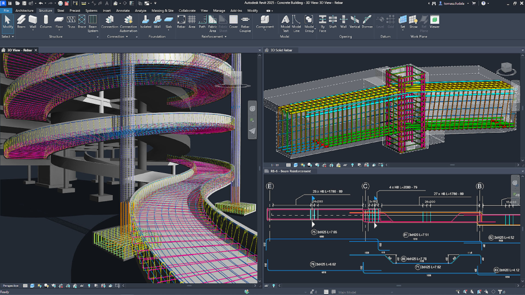
Spooling
Another VERY important thing to do also probably the most tedious boring painful thing possible is spooling. Alright so basically every pipe is a spool, like the pipe itself alongside all the components of a pipe are called spools. You create sheets showing the pipe type, the welds in a pipe, where it is in the system, just all the information about it effectively. So that its easier to fabricate in the shop, and then install in the field. As you can see down below each component is its own individual spool and contains information.

Revit Functions
Revit has several functions that elevate it above other traditional CAD programs. While they only draw shapes, Revit draws smart models, every object is a parametric component containing both geometric and non-geometric information. In essence this means that the components, called families in Revit, adjust based on user-defined parameters, so if I change a dimension or property on a family it will change to match it and update throughout the project automatically. This also allows for real time coordination between drawings and automatic updates in plans, elevations, or schedules. Particularly this is useful for updating schedules, allowing easier documentation, this is invaluable for large projects. Additionally multiple users can work on the same project through the use of worksets, in my experience though the collaboration can mess up sometimes and cause issues in the project. Revit also incorporates built in rendering tools allowing for photorealistic outputs, showing how the model will actually look once built. Revit is INVALUABLE for BIM work, I REFUSE TO WORK IN AUTOCAD I WON’T DO IT
Navisworks
Of course once you model everything in Revit you have to review what it actually looks like in 3D and make sure that your work is coordinated with everyone else thats working on the project, honestly this, called clash detection, is like half the work on any project. But Navisworks isn’t just for clash detection, its also used for 4D simulation and just bringing everyone’s work together into one model showing plumbing, ductwork, etc all together in the finished product.
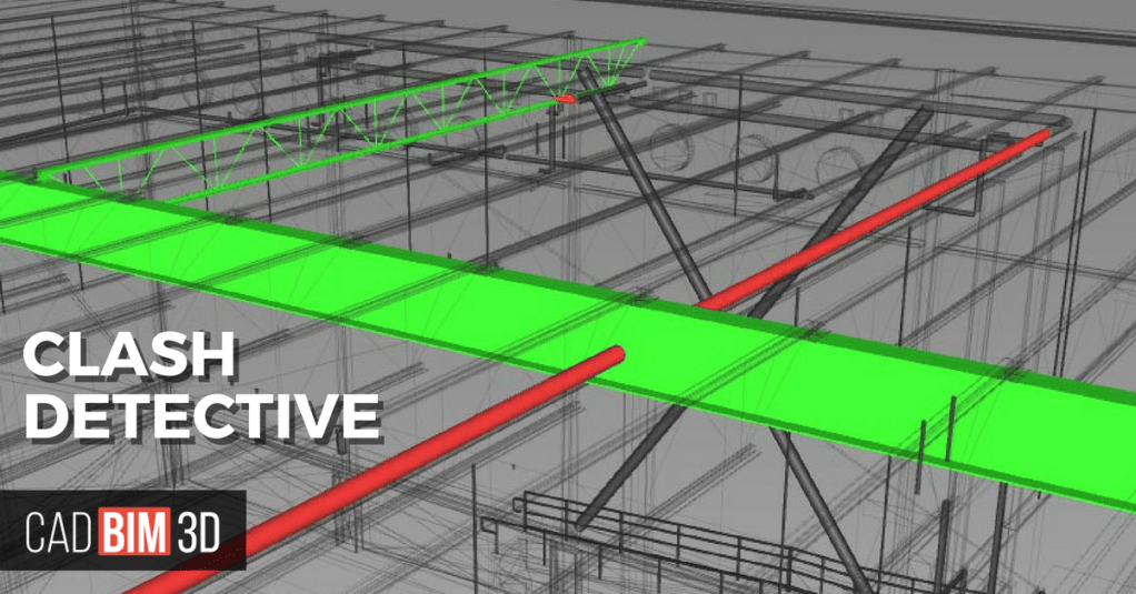
Clash Detection
To make it easier to understand what I’m saying let me describe it like this, imagine you’re going through a building and there’s a pipe hitting a door, that’s a clash and you have to fix that by either running the pipe somewhere else, or if there’s no other options you have to send in a RFI (Request for Information) to the client in order to see if there is any to fix the clash or if something more drastic needs to be done. Oftentimes the process of sending a RFI can take weeks, and can slow down your workflow significantly, and RFI is used for more than just what I described. It can be to confirm the pipes material, size, or whether the system is welded, victaulic, or literally anything else.
4D Simulation
4D simulation is really cool because it basically allows you to watch the building being built in real time in Navisworks. So you take elements from the 3D model like doors, wall, pipes, etc just everything that makes up the building. Then you link all those elements to the construction schedule which is how and when the building will be built and then it will build it right in front on you. You can watch the parts of the building being installed, how different parts overlap, and when each phase of construction happens. Beyond just being cool to see its useful for planning, coordination, and just understanding the sequencing of the building.

Thats the BIM basics, there’s so much more stuff I could go into detail on and so much more detail I could add but this is already really long and I already have a good overview based on this so I’m going to end it here. Here’s some relevant links to check out incase you want to learn more.

Leave a comment